ovo_集成_期末

看这个:

https://cmd.dayi.ink/XFSKxgKsRCah021Q0M2EEA

实训-for 期末

加油

题目:

内网

某公司企业内网,内网当中存在四个vlan ,分别为vlan10 vlan20 vlan30 vlan100

1、财务部是vlan10,并命名为caiwu

技术部是vlan20,并命名为jishu
管理部门为vlan30,并命名为guanli
内网服务器内网HTTP-SERVER单独位于vlan100,vlan名称为fuwuqi。

2、配置基本网络:

1)财务部的网段是192.168.1.0/24,网关为192.168.1.254
2)技术部的网段为192.168.2.0/24,网关为192.168.2.254
3)管理部的网段为192.168.3.0/24,网关为192.168.3.254
4)服务器的网段为172.16.1.0/24,网关为172.16.1.254
5)R1和SW1之间互联的地址为192.168.10.0/30的地址

3、现在要求所有的网关都在内网核心交换机SW1上,使用svi接口充当网关

4、实现内网所有PC和服务器之间的互联

5、由于内网员工对于计算机的使用能力较差,因此,针对财务部,技术部和管理部的终端而言,需要通过DHCP的方式自动获取IP地址(需要排除每个网段1-100的地址作为保留使用,从101开始获取),而服务器的地址由于需要固定访问,所以通过手动静态配置IP地址。(dhcp的server位于出口路由器R1上,使用dhcp的中继完成最终地址的获取)

6、允许内网管理部门的员工通过telnet管理内网的路由器和核心交换机,其他部门不允许通过telnet管理路由器和交换机。(要配置telnet管理内网设备)

公网部分

1、R1和R2之间采用100.1.1.0/24网段,R2和R3之间采用124.126.100.0/24网段地址,R3和R4之间采用202.96.137.0/24网段地址,R3和外网HTTP-SERVER以及公网PC之间,采用124.126.200.0/24网段地址。(外网HTTP-SERVER和公网PC的网关为124.126.200.254)

2、为了保证公网之间能够通信,R1、R2、R3之间采用ospf动态路由协议进行通信

3、公网PC可以通过R1的8080端口访问到内网HTTP-SERVER的80端口的http业务

4、现在有一台公网服务器HTTP-SERVER,地址为124.126.200.10/24,现在需要内网用户能够访问到该公网服务器。(R1和R2之间使用124.126.100.0/24网段)

5、有一台公网的DNS-SERVER,地址为113.100.2.56/24,网关为113.100.2.1/24,我们最终想要通过访问www.shixun.com这个域名访问到公网http-server,并且查看首页的a small page,内容显示为:welcome to study our course!

分支:

1、内网PC7和PC8分别位于vlan70和vlan80这两个vlan当中

2、PC7和PC8的网关分别为192.168.70.254 192.168.80.254,且网关位于R4路由器上

3、PC7和PC8也要能够访问外网(测试访问公网HTTP-SERVER)

内网

part1

某公司企业内网,内网当中存在四个vlan ,分别为vlan10 vlan20 vlan30 vlan100

1、财务部是vlan10,并命名为caiwu

技术部是vlan20,并命名为jishu
管理部门为vlan30,并命名为guanli
内网服务器内网HTTP-SERVER单独位于vlan100,vlan名称为fuwuqi。

2、配置基本网络:

1)财务部的网段是192.168.1.0/24,网关为192.168.1.254
2)技术部的网段为192.168.2.0/24,网关为192.168.2.254
3)管理部的网段为192.168.3.0/24,网关为192.168.3.254
4)服务器的网段为172.16.1.0/24,网关为172.16.1.254
5)R1和SW1之间互联的地址为192.168.10.0/30的地址

3、现在要求所有的网关都在内网核心交换机SW1上,使用svi接口充当网关

4、实现内网所有PC和服务器之间的互联

code

核心交换机

1
2
3
4
5
6
7
8
9
10
11
12
13
14
15
16
17
18
19
20
21
22
23
24
25
26
27
28
29
30
31
32
33
34
35
36
37
38
39
40
Switch>en
Switch#conf t
Enter configuration commands, one per line. End with CNTL/Z.
Switch(config)#hostname core
core(config)#vtp mode server
Device mode already VTP SERVER.
core(config)#vtp domain dayi
Changing VTP domain name from NULL to dayi

# 配置vlan
core(config-vlan)#vlan 10
core(config-vlan)#name caiwu
core(config-vlan)#vlan 20
core(config-vlan)#name jishu
core(config-vlan)#vlan 30
core(config-vlan)#name guanli
core(config-vlan)#vlan 100
core(config-vlan)#name fuwuqi

# 配置网关
core(config-vlan)#int vlan 10
core(config-if)#ip addr 192.168.1.254 255.255.255.0

core(config-if)#int vlan 20
core(config-if)#ip addr 192.168.2.254 255.255.255.0

core(config-if)#int vlan 30
core(config-if)#ip addr 192.168.3.254 255.255.255.0

core(config-if)#int vlan 100
core(config-if)#ip addr 172.16.1.254 255.255.255.0

# 转发
core(config)#ip routing

# 配置trunk口 _开头表示记得重点记一下_
core(config)#int range fa0/2-5
core(config-if-range)#sw trunk encap dot1q
core(config-if-range)#sw mode trunk
core(config-if-range)#sw trunk allowed _vlan_ 10,20,30,100

从交换机

  • sw = switchport

四个都这样配。

1
2
3
4
5
6
7
8
9
10
11
12
13
Switch(config)#vtp mode client
Setting device to VTP CLIENT mode.
Switch(config)#vtp domain dayi

#trunk口
Switch(config)#int fa0/1
Switch(config-if)#sw mode trunk
Switch(config-if)#sw trunk allowed vlan 10,20,30,100

#access口
Switch(config-if)#int range fa0/2-24
Switch(config-if-range)#sw mode acc
Switch(config-if-range)#sw acc vlan 100

剩下几个:

1
2
3
4
5
6
7
8
9
10
11
12
13
14
15
16
17
18
19
20
21
22
23
24
25
Switch(config)#int f0/1
Switch(config-if)#sw mode trunk
Switch(config-if)#sw trunk allowed vlan 10,20,30,100
Switch(config-if)#int range fa0/2-24
Switch(config-if-range)#sw mode acc
Switch(config-if-range)#sw acc vlan 10

vtp mode cl
vtp dom dayi
int fa0/1
sw mode trunk
sw trunk allowed vlan 10,20,30,100
int range fa0/2-24
sw mode acc
sw acc vlan 20

vtp mode cl
vtp dom dayi
int fa0/1
sw mode trunk
sw trunk allowed vlan 10,20,30,100
int range fa0/2-24
sw mode acc
sw acc vlan 30

part2

5)R1和SW1之间互联的地址为192.168.10.0/30的地址
DNS:113.100.2.56

要求

5、由于内网员工对于计算机的使用能力较差,因此,针对财务部,技术部和管理部的终端而言,需要通过DHCP的方式自动获取IP地址(需要排除每个网段1-100的地址作为保留使用,从101开始获取),而服务器的地址由于需要固定访问,所以通过手动静态配置IP地址。(dhcp的server位于出口路由器R1上,使用dhcp的中继完成最终地址的获取)

6、允许内网管理部门的员工通过telnet管理内网的路由器和核心交换机,其他部门不允许通过telnet管理路由器和交换机。(要配置telnet管理内网设备)

code

router

1
2
3
4
5
6
7
8
9
10
11
12
13
14
15
16
17
18
19
20
21
22
23
24
25
26
27
28
29
30
31
32
33
34
35
36
37
38
39
40
41
42
43
44
45
46
47
48
49
50
51
52
53
54
55
56
57
58
#IP配置
Router>en
Router#conf t
Enter configuration commands, one per line. End with CNTL/Z.
Router(config)#int g0/0
Router(config-if)#ip addr 192.168.10.1 255.255.255.252

#DHCP
Router(config)#ip dhcp exc 192.168.1.1 192.168.1.100
Router(config)#ip dhcp exc 192.168.2.1 192.168.2.100
Router(config)#ip dhcp exc 192.168.3.1 192.168.3.100


#DHCP服务器
Router(config)#ip dhcp pool VLAN10
Router(dhcp-config)#network 192.168.1.0 255.255.255.0
Router(dhcp-config)#default-router 192.168.1.254
Router(dhcp-config)#dns-server 113.100.2.56

Router(dhcp-config)#ip dhcp pool VLAN20
Router(dhcp-config)#network 192.168.2.0 255.255.255.0
Router(dhcp-config)#default-router 192.168.2.254
Router(dhcp-config)#dns-server 113.100.2.56

Router(dhcp-config)#ip dhcp pool VLAN30
Router(dhcp-config)#network 192.168.3.0 255.255.255.0
Router(dhcp-config)#default-router 192.168.3.254
Router(dhcp-config)#dns 113.100.2.56

#回到内网的路由表:
ip route 192.168.1.0 255.255.255.0 192.168.10.2
ip route 192.168.2.0 255.255.255.0 192.168.10.2
ip route 192.168.3.0 255.255.255.0 192.168.10.2
ip route 172.16.1.0 255.255.255.0 192.168.10.2

Router(config)#ip route 192.168.1.0 255.255.255.0 192.168.10.2
Router(config)#ip route 192.168.2.0 255.255.255.0 192.168.10.2
Router(config)#ip route 192.168.3.0 255.255.255.0 192.168.10.2
Router(config)#ip route 172.16.1.0 255.255.255.0 192.168.10.2


# 管理:
Router(config)#access-list 1 permit 192.168.3.0 0.0.0.255
Router(config)#access-list 1 deny any
Router(config)#line vty 0 4
Router(config-line)#login local
Router(config-line)#transport input telnet
Router(config-line)#access-class 1 in
Router(config)#username manage password cisco

# 管理-简写
Router(config)#acc 1 permit 192.168.3.0 0.0.0.255
Router(config)#line vty 0 4
Router(config-line)#login local
Router(config-line)#tran input telnet
Router(config-line)#access-class 1 in
Router(config-line)#username dayi password 123456

core

1
2
3
4
5
6
7
8
9
10
11
12
13
14
15
16
17
18
19
20
21
22
23
24
25
26
27
28
29
30
31
32
33
34
35
36
37
38
39
40
#IP配置
core(config-if-range)#vlan 500
core(config-vlan)#name core-to-router
core(config-vlan)#int vlan 500
core(config-if)#ip addr 192.168.10.2 255.255.255.252
core(config-if)#
core(config-if)#int fa0/1
core(config-if)#sw mode acc
core(config-if)#sw acc vlan 500

#DHCP ip-helper
core(config-if)#int vlan 10
core(config-if)#ip helper-addr 192.168.10.1

core(config-if)#int vlan 20
core(config-if)#ip helper-addr 192.168.10.1

core(config-if)#int vlan 30
core(config-if)#ip helper-addr 192.168.10.1


#管理:
core(config)#ip access-list standard MANAGE-IP
core(config-std-nacl)#permit 192.168.3.0 0.0.0.255
core(config-std-nacl)#exit
core(config)#line vty 0 4
core(config-line)#login local
core(config-line)#transport input telnet
core(config-line)#access-class MANAGE-IP in
core(config)#username manage password cisco

#管理-简写
core(config)#ip access-list standard
core(config-std-nacl)#permit 192.168.3.0 0.0.0.255
core(config-std-nacl)#deny any
core(config-std-nacl)#line vty 0 4
core(config-line)#login local
core(config-line)#tran input telnet
core(config-line)#access-class mangeip in
core(config-line)#username dayi password 123456

EXP-连接:

1
2
3
4
5
6
7
8
9
10
11
C:\>telnet 192.168.10.2 #交换机
Trying 192.168.10.2 ...Open


User Access Verification

Username: dayi
Password: 123456


Part3-公网

公网部分

1、R1和R2之间采用100.1.1.0/24网段,R2和R3之间采用124.126.100.0/24网段地址,R3和R4之间采用202.96.137.0/24网段地址,R3和外网HTTP-SERVER以及公网PC之间,采用124.126.200.0/24网段地址。(外网HTTP-SERVER和公网PC的网关为124.126.200.254)

2、为了保证公网之间能够通信,R1、R2、R3之间采用ospf动态路由协议进行通信

3、公网PC可以通过R1的8080端口访问到内网HTTP-SERVER的80端口的http业务

4、现在有一台公网服务器HTTP-SERVER,地址为124.126.200.10/24,现在需要内网用户能够访问到该公网服务器。(R1和R2之间使用124.126.100.0/24网段)

5、有一台公网的DNS-SERVER,地址为113.100.2.56/24,网关为113.100.2.1/24,我们最终想要通过访问www.shixun.com这个域名访问到公网http-server,并且查看首页的a small page,内容显示为:welcome to study our course!

OSPF-code

1
2
3
4
5
6
7
8
9
10
11
12
13
14
15
16
17
18
19
20
21
22
23
24
25
26
27
28
29
30
31
32
33
34
35
36
37
38
39
40
41
42
43
44
45
46
47
48
49
50
51
52
53
54
55
56
57
58
59
60
61
62
63
64
65
66
67
68
69
70
71
72
73
# INT
r1(config)#int g0/1
r1(config-if)#ip addr 100.1.1.1 255.255.255.0
r1(config-if)#no shut

#OSPF
router ospf 1
router-id 1.1.1.1 #可选
network 100.1.1.0 0.0.0.255 area 0

----具体:

#IP地址分配
r1(config)#int g0/1
r1(config-if)#ip addr 100.1.1.1 255.255.255.0
r1(config-if)#no shut

#R2 3个IP
r2(config)#int g0/0
r2(config-if)#ip addr 100.1.1.2 255.255.255.0
r2(config-if)#no shut

#R2->DHCP
r2(config-if)#int g0/2
r2(config-if)#ip addr 113.100.2.1 255.255.255.0
r2(config-if)#no shut

r2(config)#int g0/1
r2(config-if)#ip addr 124.126.100.1 255.255.255.0
r2(config-if)#no shut

#R3 2个IP
r3(config)#int g0/0
r3(config-if)#ip addr 124.126.100.2 255.255.255.0
r3(config-if)#no shut
r3(config-if)#int g0/2
r3(config-if)#ip addr 124.126.200.254 255.255.255.0
r3(config-if)#no shut

#R3->R4
r3(config)#int g0/1
r3(config-if)#ip addr 202.96.137.1 255.255.255.0
r3(config-if)#no shut

r4(config-if)#int g0/0
r4(config-if)#ip addr 202.96.137.2 255.255.255.0
r4(config-if)#no shut


# OSPF具体:
r1(config)#router ospf 1
r1(config-router)#router-id 1.1.1.1
r1(config-router)#network 100.1.1.0 0.0.0.255 area 0

r2(config-if)#route ospf 1
r2(config-router)#router-id 2.2.2.2
r2(config-router)#network 100.1.1.0 255.255.255.0 area 0
r2(config-router)#network 124.126.100.0 255.255.255.0 area 0
r2(config-router)#network 113.100.2.0 255.255.255.0 area 1

r3(config-if)#router ospf 1
r3(config-router)#route
r3(config-router)#router-id 3.3.3.3
r3(config-router)#network 124.126.100.0 255.255.255.0 area 0
r3(config-router)#network 202.96.137.0 255.255.255.0 area 0
r3(config-router)#network 124.126.200.0 0.0.0.255 area 0

r4(config-if)#router ospf 1
r4(config-router)#router-id 4.4.4.4
r4(config-router)#network 202.96.137.2 255.255.255.0 area 0

NAT-code

1
2
3
4
5
6
7
8
9
10
11
12
core(config)#ip route 0.0.0.0 0.0.0.0 192.168.10.1

r1(config)#access-list 10 permit 172.16.1.0 0.0.0.255
access-list 10 permit 192.168.1.0 0.0.0.255
access-list 10 permit 192.168.2.0 0.0.0.255
access-list 10 permit 192.168.3.0 0.0.0.255
r1(config)#int g0/0
r1(config-if)#ip nat inside
r1(config-if)#int g0/1
r1(config-if)#ip nat outside
r1(config-if)#ip nat inside source list 10 int g0/1 overload
r1(config)#ip nat inside source static tcp 172.16.1.100 80 100.1.1.1 8080

PART4-分支:

要求:

分支:

1、内网PC7和PC8分别位于vlan70和vlan80这两个vlan当中

2、PC7和PC8的网关分别为192.168.70.254 192.168.80.254,且网关位于R4路由器上

3、PC7和PC8也要能够访问外网(测试访问公网HTTP-SERVER)

CODE-PART

1
2
3
4
5
6
7
8
9
10
11
12
13
14
15
16
17
18
19
20
21
22
23
24
25
26
27
28
29
30
31
32
33
34
35
36
37
38
39
r4(config-subif)#int g0/1.70
r4(config-subif)#encap dot1q 70
r4(config-subif)#ip addr 192.168.70.254 255.255.255.0

r4(config-subif)#int g0/1.80
r4(config-subif)#encap dot1q 80
r4(config-subif)#ip addr 192.168.80.254 255.255.255.0


core-brench(config)#vlan 70
core-brench(config-vlan)#vlan 80

core-brench(config-vlan)#int fa0/2
core-brench(config-if)#sw mode acc
core-brench(config-if)#sw acc vlan 70
core-brench(config-if)#int fa0/3
core-brench(config-if)#sw mode acc
core-brench(config-if)#sw acc vlan 80

core-brench(config-if)#int f0/1
core-brench(config-if)#sw trunk encapsulation dot1q
core-brench(config-if)#sw mode trunk

core-brench(config-if)#sw trunk allowed vlan 70,80


#NAT
r4(config-subif)#access-list 100 permit ip 192.168.70.0 0.0.0.255 any
r4(config)#access-list 100 permit ip 192.168.80.0 0.0.0.255 any
r4(config)#ip nat inside source list 100 int g0/0 overload
r4(config)#int g0/0
r4(config-if)#ip nat outside
r4(config-if)#int g0/1
r4(config-if)#ip nat inside

r4(config-if)#int g0/1.70
r4(config-subif)#ip nat inside
r4(config-subif)#int g0/1.80
r4(config-subif)#ip nat inside

命令汇总

核心

1
2
3
4
5
6
7
8
9
10
11
12
13
14
15
16
17
18
19
20
21
22
23
24
25
26
27
28
29
30
31
32
33
34
35
36
37
38
39
40
41
42
43
44
45
46
47
48
49
50
51
52
53
54
55
56
57
58
59
60
61
62
63
64
65
66
67
68
# 核心交换机,内网

hostname core
ip routing
username dayi password 0 123456

interface FastEthernet0/1
switchport access vlan 500
switchport mode access
switchport nonegotiate
!
interface FastEthernet0/2
switchport trunk allowed vlan 10,20,30,100
switchport trunk encapsulation dot1q
switchport mode trunk
!
interface FastEthernet0/3
switchport trunk allowed vlan 10,20,30,100
switchport trunk encapsulation dot1q
switchport mode trunk
!
interface FastEthernet0/4
switchport trunk allowed vlan 10,20,30,100
switchport trunk encapsulation dot1q
switchport mode trunk
!
interface FastEthernet0/5
switchport trunk allowed vlan 10,20,30,100
switchport trunk encapsulation dot1q
switchport mode trunk

interface Vlan1
no ip address
shutdown
!
interface Vlan10
mac-address 00e0.f9a6.9c01
ip address 192.168.1.254 255.255.255.0
ip helper-address 192.168.10.1
!
interface Vlan20
mac-address 00e0.f9a6.9c02
ip address 192.168.2.254 255.255.255.0
ip helper-address 192.168.10.1
!
interface Vlan30
mac-address 00e0.f9a6.9c03
ip address 192.168.3.254 255.255.255.0
ip helper-address 192.168.10.1
!
interface Vlan100
mac-address 00e0.f9a6.9c04
ip address 172.16.1.254 255.255.255.0
!
interface Vlan500
mac-address 00e0.f9a6.9c05
ip address 192.168.10.2 255.255.255.252

ip route 0.0.0.0 0.0.0.0 192.168.10.1

ip access-list standard mangeip
permit 192.168.3.0 0.0.0.255
deny any

line vty 0 4
access-class mangeip in
login local
transport input telnet

R1路由器

1
2
3
4
5
6
7
8
9
10
11
12
13
14
15
16
17
18
19
20
21
22
23
24
25
26
27
28
29
30
31
32
33
34
35
36
37
38
39
40
41
42
43
44
45
46
47
48
49
50
51
52
53
54
55
56
57
58
59
60
61
62
63
64
65
66
67
68
69
hostname r1

ip dhcp excluded-address 192.168.1.1 192.168.1.100
ip dhcp excluded-address 192.168.2.1 192.168.2.100
ip dhcp excluded-address 192.168.3.1 192.168.3.100
!
ip dhcp pool VLAN10
network 192.168.1.0 255.255.255.0
default-router 192.168.1.254
dns-server 113.100.2.56
ip dhcp pool VLAN20
network 192.168.2.0 255.255.255.0
default-router 192.168.2.254
dns-server 113.100.2.56
ip dhcp pool VLAN30
network 192.168.3.0 255.255.255.0
default-router 192.168.3.254
dns-server 113.100.2.56

!
username dayi password 0 123456

interface GigabitEthernet0/0
ip address 192.168.10.1 255.255.255.252
ip nat inside
duplex auto
speed auto
!
interface GigabitEthernet0/1
ip address 100.1.1.1 255.255.255.0
ip nat outside
duplex auto
speed auto
!
interface GigabitEthernet0/2
no ip address
duplex auto
speed auto
shutdown

router ospf 1
router-id 1.1.1.1
log-adjacency-changes
network 100.1.1.0 0.0.0.255 area 0
!
ip nat inside source list 10 interface GigabitEthernet0/1 overload
ip nat inside source static tcp 172.16.1.100 80 100.1.1.1 8080

ip route 192.168.1.0 255.255.255.0 192.168.10.2
ip route 192.168.2.0 255.255.255.0 192.168.10.2
ip route 192.168.3.0 255.255.255.0 192.168.10.2
ip route 172.16.1.0 255.255.255.0 192.168.10.2

access-list 1 permit 192.168.3.0 0.0.0.255
access-list 1 deny any
access-list 10 permit 172.16.1.0 0.0.0.255
access-list 10 permit 192.168.20.0 0.0.0.255
access-list 10 permit 192.168.30.0 0.0.0.255
access-list 10 permit 192.168.1.0 0.0.0.255
access-list 10 permit 192.168.2.0 0.0.0.255
access-list 10 permit 192.168.3.0 0.0.0.255

line vty 0 4
access-class 1 in
login local
transport input telnet


R2路由器

1
2
3
4
5
6
7
8
9
10
11
12
13
14
15
16
17
18
19
20
21
22
23
hostname r2

interface GigabitEthernet0/0
ip address 100.1.1.2 255.255.255.0
duplex auto
speed auto
!
interface GigabitEthernet0/1
ip address 124.126.100.1 255.255.255.0
duplex auto
speed auto
!
interface GigabitEthernet0/2
ip address 113.100.2.1 255.255.255.0
duplex auto
speed auto

router ospf 1
router-id 2.2.2.2
log-adjacency-changes
network 100.1.1.0 0.0.0.255 area 0
network 124.126.100.0 0.0.0.255 area 0
network 113.100.2.0 0.0.0.255 area 1

R3路由器

1
2
3
4
5
6
7
8
9
10
11
12
13
14
15
16
17
18
19
20
21
22
23
24
25
hostname r3

int g0/0
ip addr 124.126.100.2 255.255.255.0
duplex auto
speed auto
!
int g0/1
ip addr 202.96.137.1 255.255.255.0
duplex auto
speed auto
!
int g0/2
ip addr 124.126.200.254 255.255.255.0
duplex auto
speed auto

router ospf 1
router-id 3.3.3.3
log-adjacency-changes
network 124.126.100.0 0.0.0.255 area 0
network 202.96.137.0 0.0.0.255 area 0
network 124.126.200.0 0.0.0.255 area 0


R4

1
2
3
4
5
6
7
8
9
10
11
12
13
14
15
16
17
18
19
20
21
22
23
24
25
26
27
28
29
30
31
32
33
34
35
36
37
38
hostname r4
!
!
int g0/0
ip addr 202.96.137.2 255.255.255.0
ip nat outside
duplex auto
speed auto
!
int g0/1
no ip addr
ip nat inside
duplex auto
speed auto
!
int g0/1.70
encapsulation dot1Q 70
ip addr 192.168.70.254 255.255.255.0
ip nat inside
!
int g0/1.80
encapsulation dot1Q 80
ip addr 192.168.80.254 255.255.255.0
ip nat inside
!

router ospf 1
router-id 4.4.4.4
log-adjacency-changes
network 202.96.137.0 0.0.0.255 area 0
!
ip nat inside source list 100 int g0/0 overload

access-list 100 permit ip 192.168.70.0 0.0.0.255 any
access-list 100 permit ip 192.168.80.0 0.0.0.255 any


分支交换机

1
2
3
4
5
6
7
8
9
10
11
12
13
14
15
16
hostname core-brench
!
interface FastEthernet0/1
switchport trunk allowed vlan 70,80
switchport trunk encapsulation dot1q
switchport mode trunk
!
interface FastEthernet0/2
switchport access vlan 70
switchport mode access
switchport nonegotiate
!
interface FastEthernet0/3
switchport access vlan 80
switchport mode access
switchport nonegotiate

0XFF-文件

https://p.dabbit.net/blog/pic_bed/sharex/2024-07-11-01-59-08_Mongoose_Red_Sandy_3_1720634348_Copepod.rar

https://p.dabbit.net/blog/pic_bed/sharex/2024-07-11-02-05-34_Queenslandgrouper_Humiliating_Utilized_4_1720634734_Zorilla.rar

WORD:
https://p.dabbit.net/blog/pic_bed/sharex/2024-07-11-18-26-27_Zeren_Darkturquoise_Brilliant_5_1720693587_Kodiakbear.pdf

EXP:

1.全工模式、速率、auto-MDIX;

1
2
3
4
5
Router(config)#int g0/0/0
Router(config-if)#mdix auto
Router(config-if)#duplex full
Router(config-if)#speed 100
Router(config-if)#end

2.使用vty线路进行SSH登录;

1
2
3
4
5
6
7
8
9
10
11
12
13
14
15
16
17
18
19
20
21
22
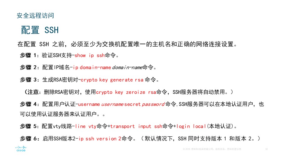
Router(config)#ip domain-name example.com #配置ip域名
Router(config)#ip ssh version 2 #配置ssh版本2
Please create RSA keys (of at least 768 bits size) to enable SSH v2.
Router(config)#crypto key generate rsa
% Please define a hostname other than Router.
Router(config)#hostname r1 #记得先重命名
r1(config)#crypto key generate rsa #生成rsa密钥对
The name for the keys will be: s1.example.com
Choose the size of the key modulus in the range of 360 to 4096 for your
General Purpose Keys. Choosing a key modulus greater than 512 may take
a few minutes.

How many bits in the modulus [512]: 512
% Generating 512 bit RSA keys, keys will be non-exportable...[OK]

r1(config)#username admin secret ccna #用户admin分配的密码是ccna
*Mar 1 0:1:55.42: RSA key size needs to be at least 768 bits for ssh version 2
*Mar 1 0:1:55.42: %SSH-5-ENABLED: SSH 1.5 has been enabled
r1(config)#line vty 0 15 #配置VTY范围0-15
r1(config-line)#transport input ssh #在VTY上启用SSH的命令
r1(config-line)#login local #设置用户本地验证
Router(config)#ip ssh version 2 #启动

3.路由器特权模式密码、环回接口设置;

进入控制台配置模式的命令是(),设置控制台连接密码为cisco并启用该密码的命令是()和()
(1) line console 0
(2) password cisco
(3) login

设置特权模式密码为class的命令是()。
(1) enable secret class

设置环回接口

1
2
Router(config)#interface loopback 1
Router(config-if)#ip address ip 子网掩码
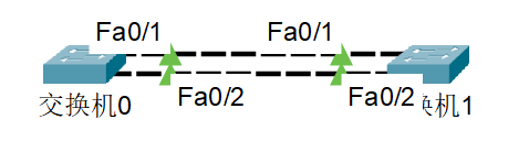
4.配置以太通道;

1
2
3
4
5
6
7
8
9
10
11
12
13
s1(config)#interface range fa0/1 - 2 #对fa0/1与fa0/2口设置
s1(config-if-range)#channel-group 1 mode active #用PAgP模式的话把active改为desirable

s1(config-if-range)#exit
s1(config)#interface port-channel 1 #创建以太通道后,系统会增加一个名称为Port-channel 1的端口
s1(config-if)#sw mode trunk #设置为中继端口

s2(config)#interface range fa0/1 - 2 #与S1进行相同操作
s2(config-if-range)#channel-group 1 mode active #同理
s2(config-if-range)#exit
s2(config)#int port-channel 1
s2(config-if)#sw mode trunk
s2(config-if)#exit

NAT-pool

1
2
3
4
5
6
7
8
9
10
11
Router(config)#int g0/1
Router(config-if)#ip nat outside
Router(config-if)#ip addr 12.1.1.1 255.255.255.0

Router(config-if)#ip nat pool gongwang 12.1.1.10 12.1.1.12 netmask 255.255.255.0
Router(config)#ip nat inside source list 10 pool gongwang
Router(config)#ip nat inside source static 192.168.3.1 12.1.1.1
Router(config)#ip route 0.0.0.0 0.0.0.0 12.1.1.2
Router(config)#access-list 10 permit 192.168.1.0 0.0.0.255
Router(config)#access-list 10 permit 192.168.2.0 0.0.0.255
Router(config)#access-list 10 permit 192.168.3.0 0.0.0.255

大二实训

1、左边为公司企业内网,内网当中存在四个vlan ,分别为vlan10 vlan20 vlan30 vlan40,vlan10为财务部,vlan20为业务部,vlan30为技术部 vlan40为服务器
2、pc0和pc1为财务部,pc2和pc3为业务部,server1为内网服务器。
财务部的网段为192.168.10.0/24
业务部的网段为192.168.20.0/24
技术部的网段为192.168.30.0/24
服务器的网段为172.16.1.0/24,且服务器的地址为172.16.1.100/24
3、所有终端的网关均位于内网3560这台switch0交换机上(以vlanif作为网关),且网关地址均为254.
4、由于财务部和业务部员工计算机使用能力较差,所以他们获取地址的方式采用DHCP(可以在3560上做,也可以在router0上做(router0上要做单臂路由)),而技术部员工计算机使用熟练,需手动配置地址,地址自由赋予
5、内网终端pc0–pc5均能够访问到内网server1,并且能够访问外网的server0(配置源地址转换即超载nat)

公网部分
1、router0和router1之间采用100.1.1.0/24网段,router1和router2之间采用124.126.100.0/24网段地址,router2和server0以及pc6之间,采用124.126.200.0/24网段地址
2、为了保证公网之间能够通信,router0 router1 和router2之间采用ospf动态路由协议
3、公网PC6可以通过router0的8080端口访问到内网server1的80端口的http业务